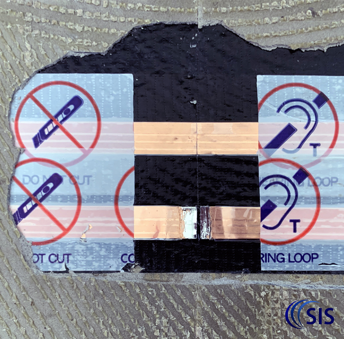
We receive many calls from panicked contractors that have accidentally damaged an induction loop (foil) tape. We have created this quick guide on how to repair the damage in four easy steps.
An Audio Frequency Induction Loop System (A.F.I.L.S.) is an assistive listening system for those who experience hearing loss and use a hearing aid. A system comprises an audio input source (either from a microphone or sound system), amplifier(s) and copper tape/cable, which is normally run around the perimeter of the area that needs to be covered by the system. A hearing aid user switches their hearing aid to the ‘T’ (telecoil) programme to hear the audio direct into their hearing aid.
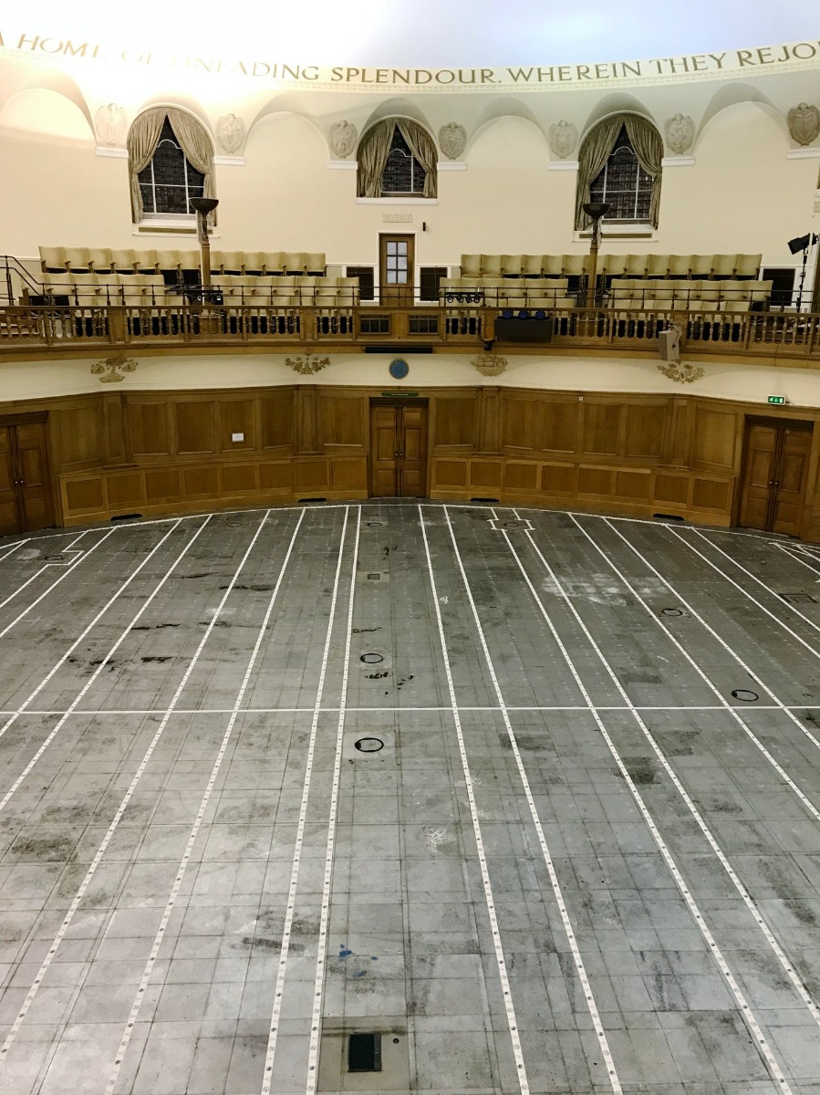
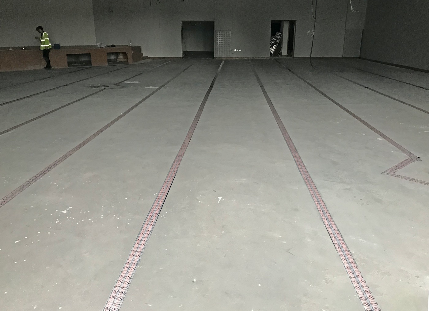
There are different types of induction loop systems but generally tape/cable is only used in induction loop systems that cover a complete room or area. Induction loop tape is used instead of cable under floor coverings such as carpets, vinyl and laminates due to its low profile.
Induction loop tape is normally covered with a warning tape to warn contractors to take care not to damage it, but as this is normally under the floor material (carpet, vinyl, etc) it is often hidden. The tape is made of insulated copper and is normally sandwiched between two layers of Gaffa (tank) tape. This is only used to stop the copper tape moving during installation so provides no protection from knives or other tools. Damage can occur very easily when lifting the floor material especially if it has been glued down.
For an induction loop to function, the tape must be intact. If the tape is damaged or cut, the amplifier will normally detect a fault and shut down.
Step 1. Check the loop
The induction loop tape will be connected to a cable at each end to enable it to connect to the induction loop amplifier. This will either be by binding posts or a plug on the rear of the amplifier. Remove the cable from the amplifier (marking the polarity if the amplifier has two outputs or two or more amplifiers are present).
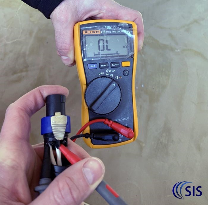
Use an Ohm meter or multi-meter programmed to measure resistance, to check if the induction loop is open circuit (i.e. does not display a resistance due to not forming a compete circuit). If there are two amplifiers (or one amplifier that has two outputs) feeding the same area, then it can be useful to compare the resistance of the two loops, as they would normally be the same. A typical resistance should be between 0.5-2.5 Ω (Ohms).
If there is no or very high resistance, then the tape has been damaged.
Tip. Make sure the ohm meter/multi-meter prongs make a good contact on the induction loop cable to not give a false reading.
Step 2. Find the damage
This can be very difficult but always start where any building work has recently been carried out. If there is no obvious area where the loop tape has been disturbed, then try and trace the tape and start the testing continuity in different areas. If loop tape is installed around the perimeter then start testing for resistance between each corner of the room. If you only have a resistance reading on three sides, then the damage will be between the corners where you cannot see a reading.
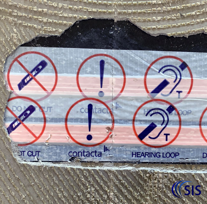
Often damage occurs in more than one place, so if you repair one section and the loop still has high or no resistance then keep looking for more damage!
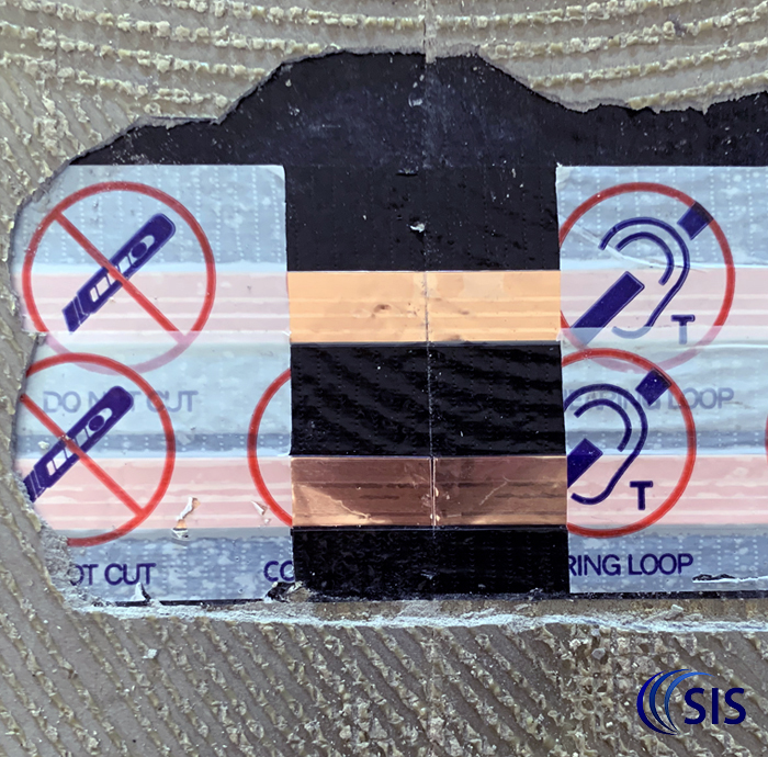
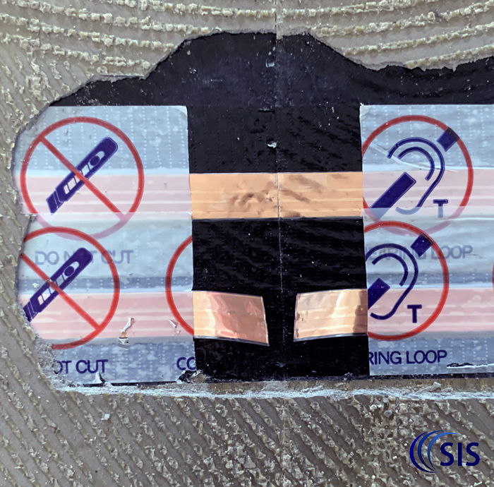
Once you find the damage, carefully remove the warning and Gaffa tape to access the copper foil.
Tip. Sometimes a carpet knife can make a clean cut of the tape which can cause variable results causing the loop to be intermittent. One way to help locate this damage is to have somebody watching the meter while another shuffles their feet around the carpet route above where the loop tape has been installed. If the resistance suddenly changes when over a specific area of the carpet, then the loop tape is likely to be damaged underneath.
Only one of the of the induction loop tapes in this photo was damaged. Despite the knife marking the second tape, the tape (and it’s clear insulation) were intact.
Step 3. Repair the damaged tape
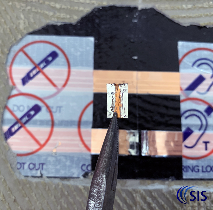
Use a sharp blade to carefully scrape approximately 20mm of the clear outer insulation from the loop tape to expose clean copper. Use a soldering iron and solder to tin each end of the loop tape.
Cut a small piece of loop tape, carefully scraping the clear outer insulation on each side, before tinning it with solder. This piece of loop tape should be long enough to span the damage on the installed tape. Place a new piece of tape over the damaged piece and solder them together, one side at a time.
The loop tape used to repair the damage should be the same size as the installed tape.
Tip. Place a thin sheet of stainless steel (or similar) under the foil (not shown) when soldering it so not to damage the surrounding Gaffa/tank/warning tape or surrounding materials.
Step 4. Test the repair
Reconnect the ohm meter/multi-meter to the ends of the loop and recheck the resistance. If the resistance is now correct, then you can re-insulate the loop tape with Gaffa/tank tape. Once covered, reconnect the induction loop cable to the amplifier and switch it on.
To test the induction loop, an input must be feeding the amplifier(s). Indicators will flash across the amplifier’s output screen to show there is current flowing around the loop. A loop test receiver should then be used to listen to the loop system to check the audio is clear and free of distortion.
(A loop test receiver is a compact battery powered device that simulates a hearing aid set to the ‘T’ programme. Headphones are plugged into the receiver to hear the audio)
The induction loop receiver should be held approximately 1.2m from the floor, if the area is normally used by people that are seated e.g. a church, or 1.7m for an area normally used by people that are standing e.g. a concert venue. Most receivers should be held in the vertical position.
Warning tape should be placed back over the loop tape to warn other contractors!
Popular induction loop receivers are-
Contacta IL-RX 20
Induction loop foil and warning tape can be purchased here.


